Please choose from the options below to proceed.
If you do not find the answer to your question within this FAQs section, please contact us for further assistance.
Or for further information on sizing ventilation, download our technical document.
Domestic Ventilation
General fan questions
The fan or fan and shutters do not work?
Is it within the warranty period?
Yes
If the product has been installed in accordance with the fitting/wiring instructions and there is a supply at the fan but it does not work, then return to the place of purchase for a replacement.
No
Check there is a stable supply to the fan and that the impeller is able to spin freely and there is no blockage within the fan and any duct run or termination.
Check nothing is obstructing the shutter mechanism
Fan works but the shutters are not opening?
Is it within the warranty period
Yes
If the product has been installed in accordance with the fitting/wiring instructions and there is a supply at the fan but the shutters or shutter and fan do not work, then return to the place of purchase for a replacement.
No
Check there is a stable supply to the fan. If possible, check that there is no obstruction to the shutter mechanism and blades.
How do I clean my fan?
The product instructions will normally give guidance on fan maintenance so please check those in addition to the following information.
Otherwise after ensuring that the fan is safely isolated from the mains supply, periodically check the fan is free of any dust/dirt/grease build up using a damp cloth with warm water and a mild detergent.
How do I mount a fan?
Window Mount
Your glazing specialist must prepare glazing - all other details are found in the relevant fitting and wiring instructions supplied with the product or available online
Wall Mounting
Core cut the relevant size hole, full details are in the relevant F&W
Where can I get a copy of the fan fitting/wiring instructions?
Visit our installation instructions section
What is the guarantee period for my product?
For more information, go to our product guarantee page
How much ducting can I attach to my fan?
A common question, and the guidance below is more relevant to domestic-type installations.
Domestic Axial fans
An axial fan has a fan blade like a ship propeller. These are low-pressure fans and a general rule of thumb for these is to use no more than 1.5 metres of ducting. On a 100mm fan/ducting system, a 90 degree bend is equivalent to 1 metre, preferably rigid duct. For longer runs, a centrifugal-type fan should be considered.
Domestic Centrifugal fans
A Centrifugal fan has a fan blade like a hamster wheel. The question of duct run length becomes more difficult here. Centrifugal fans are higher pressure fans and so cope better with ducted runs or where installations are in exposed positions such as an external wall prone to strong gusty winds. To know how far a Centrifugal fan is going to push the air means knowing the overall system resistance/pressure - Anything in the path of the airflow causes a resistance - this could be ducting straight lengths, bends, filters, grilles etc..... In a domestic wet room, you need to consider a Centrifugal fan once you are over 1.5 meters of ducting, but you must still ensure that the chosen fan will achieve the required airflow for the room being ventilated with the system resistance taken into account.
Can I put more than one fan into a common duct?
You should not put more than one fan into a common duct.
Each fan should have its own duct run to the atmosphere. If you try to combine them into a common duct it will bring with it a number of problems, including an unbalanced system with positive/negative air pressures which play havoc with the fan motors and could cause motor failure. It can also cause cross-contamination issues.
Also, not to forget that incorrect installation of the fan could void the product warranty.
In residential and some commercial applications, an alternative to multiple fans into common ducts could be a Central Extract System Fan
Humidity control specific questions
The humidity sensor does not bring the fan on
It may be that the humidity level within the room is not high enough to trigger the fan. Where necessary, with most humidity fans you can adjust the sensitivity of the humidity sensor. See product fitting/wiring instructions for guidance.
The humidity sensor is making the fan run for long periods of time
Where necessary, with most humidity fans you can adjust the sensitivity of the humidity sensor. See product fitting/wiring instructions for guidance. Normal ambient humidity levels on a given day can trigger a humidity fan in just the same way as humidity generated by steam from the bath/shower room or Kitchen if the humidity level rises above the set point. New build properties, as well as refurbished/redecorated properties, will go through a drying out stage during which the dampness being drawn out from walls, ceilings etc is going to affect the humidity level within the room, and a fan humidity sensor will trigger if the humidity level rises above the set-point.
Timer control specific questions
The timer does not run-on at all
Ensure the fan has been wired in accordance with the fitting/wiring instructions. Timer fans require a permanent live and neutral and a switch live to operate correctly.
The timer does not time out and so the fan runs on continuously
- My fan is controlled by the light switch
- My lighting is low voltage or low energy and has its own transformer
Ensure there is both a permanent live and switch live on the fan or transformer controller (where applicable) and that they have been connected to the correct way round. See product fitting/wiring for full relevant wiring details. Some types of low voltage and low energy lighting (mainly older types) can create a high voltage surge at the point the light is switched and this can interfere with and in some cases damage timers in fans. If your timer fan has failed due to lighting type, you will likely need to replace it. If placed on the same lighting circuit, your electrical should protect the fan with a suppression device such as a Varistor of the type relevant to the lighting type. - My light does not have a transformer or is a tungsten filament light bulb
Ensure there is both a permanent live and switch live on the fan or transformer controller (where applicable) and that they have been connected to the correct way round. See product fitting/wiring for full relevant wiring details.
- My lighting is low voltage or low energy and has its own transformer
- My fan is controlled by a switch other than a light switch
Ensure there is both a permanent live and switch live on the fan or transformer controller (where applicable) and that they have been connected to the correct way round. See product fitting/wiring for full relevant wiring details.
How do I adjust the run-on timer?
Run-on timers can usually be adjusted between approximately 3 - 30 mins (this range varies depending on the fan). See product fitting/wiring for guidance
Heat Recovery specific questions
How to clean my domestic Heat Recovery unit?
WARNING: THE FAN AND ANCILLARY CONTROL EQUIPMENT MUST BE ISOLATED FROM THE POWER SUPPLY DURING MAINTENANCE.
1. At intervals appropriate to the installation, the fan should be inspected and cleaned to ensure there is no build up of dirt or other deposits.
2. Wipe the inlets and front face with a damp cloth until clean. The fan has sealed for life bearings, which do not require lubrication.
In addition to the guidance above - Please click here for additional instructions on cleaning of heat recovery units.
Commercial Ventilation
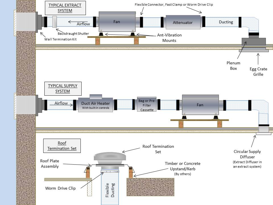
Typical Accessories for Inline fans with Circular Connections
The below highlights typical accessories and part numbers used with Inline fans with circular connections/spigots between 100-500mm. The parts list is not exhaustive, but we hope it will be of assistance with general selections. The pdf download also includes a couple of typical installation drawings to show how and where the accessories might be fitted within a ducted system.
| InLine Fan Size (mm) | Antivibration Mounts (Set of 4) | Flexible Connectors | Worm Drive Clips | PVC Flexible Ducting (6m length) | Aluminium Flexible Ducting (10m Length) | Backdraught Shutter | Silencer (Attenuator) 300mm | Silencer (Attenuator) 600mm | Silencer (Attenuator) 900mm | Silencer (Attenuator) 1200mm |
|---|---|---|---|---|---|---|---|---|---|---|
| 100 | AVM220 | FLX100 | 561704 | 436580 | 10539100 | 10542100 | 10534100 | 10535100 | 10536100 | ------- |
| 125 | AVM220 | FLX125 | 561707 | 436584 | 10539125 | 10542125 | 10534125 | 10535125 | 10536125 | ------- |
| 150 | AVM220 | FLX150 | 561707 | 436588 | 10539150 | 10542150 | 10534150 | 10535150 | 10536150 | ------- |
| 200 | AVM220 | FLX200 | 561710 | 436592 | 10539200 | 10542200 | ------- | 10535200 | 10536200 | 10537200 |
| 250 | AVM220 | FLX250 | 561710 | ------- | 10539250 | 10542250 | ------- | 10535250 | 10536250 | 10537250 |
| 315 | AVM220 | FLX315 | 561715 | ------- | 10539315 | 10542315 | ------- | 10535315 | 10536315 | 10537315 |
| 400 | AVM220 | FLX400 | 561720 | 566616 | ------- | ------- | ------- | 10535400 | 10536400 | 10537400 |
| 500 | AVM220 | FLX500 | 561720 | ------- | ------- | ------- | ------- | ------- | 10536500 | 10537500 |
| InLine Fan Size (mm) | Circular Diffusers Extract (Stale air out) | Circular Diffusers Intake (Fresh air in) | Plenum Box | Egg Crate Grille (White) | Wall Termination Set | Roof Termination Set | Roof Plate Assembly | Duct Air Heater (with built in Controls) | Pre-Filter Cassette | Bag-Filter Cassette |
|---|---|---|---|---|---|---|---|---|---|---|
| 100 | 10544100A | 10543100A | 560856 | 560846 | W10554150 | 10555150 | 560135 | 10531100T1 | 10532100A | 10533100 |
| 125 | 10544125A | 10543125A | 560601 | 560847 | W10554150 | 10555150 | 560135 | 10531125T1 | 10532125A | 10533125 |
| 150 | 10544150A | 10543150A | 560602 | 560848 | W10554150 | 10555150 | 560135 | 10531150T1 | 10532150A | 10533150 |
| 200 | 10544200A | 10544200A | 560603 | 560849 | W10554200 | 10555200 | 560137 | 10531200T1 | 10532200A | 10533200 |
| 250 | ------- | ------- | 560604 | 560849 | W10554250 | 10555250 | 560139 | 10531250T1 | 10532250A | 10533250 |
| 315 | ------- | ------- | 560605 | 560850 | W10554315 | 10555315 | 560142 | 10531315T1* | 10532315A | 10533315 |
| 400 | ------- | ------- | 560605 | 560850 | ------- | 560164 | 560142 | 10531400T3* | 10532400A | 10533400 |
| 500 | ------- | ------- | ------- | ------- | ------- | ------- | ------- | 10531500T3* | 10532500A | 10533500 |
T-Series Matching Controllers & Typical Accessories
Click here to display a list of Controls and typical accessories and part numbers used with the T-Series Range Fans.
The parts list is not exhaustive, but we hope it will be of assistance with general selections.
The pdf also includes a typical installation drawing to show how and where some of the accessories might be fitted. We hope to add further examples in due course.
Specific Fan Power (SFP)
We are often asked for the specific fan power (SFP) for a given fan. This is usually given at duty point, and so you would need to know the design airflow and system pressure for your application.
If you have the design duty, then you can try entering this on our Fan Selection Program, then use the filters to tailor your fan selection, and as you will see, the selection program will give you the specific fan power.
The fan selector will not contain older products, and where the information isn't within the fan selection program, you can obtain a rough guide by formula.
Specific Fan Power (SFP) = watts/ litres per second
How do I install the Airflow Shutter with my new Standard Range Window Fan?
With the introduction of the Mark 3 Standard Range motor back in 2010, the installation of the airflow shutter has changed.
In years past, you could install the Airflow shutter over the pre-installed motor, however due to the design of the Mark 3 motor, you must first remove the motor to fit the shutter assembly.
Click here for a step-by-step guide on installation of the Standard Range shutter assembly in the Window Fan.